Introduction:
Welcome to my blog post! Recently, I had the opportunity to dive into the world of 6502 Assembly Language through a lab assignment. In this post, I'll take you through my experience with the lab, share the insights I gained, and explore the fascinating realm of low-level programming.
Lab 1: Overview and Setup
The first step of the lab involved setting up the 6502 emulator and loading the provided code. This allowed me to interact with the bitmapped display and experiment with different assembly language instructions.
Bitmap Code: Understanding and Experimentation
The core of the lab was the provided code snippet for filling the bitmapped display with yellow color. By analyzing each instruction and experimenting with code modifications, I gained a deeper understanding of assembly language concepts and their visual impact on the display.
After that to perform the next part of the lab to optimize the code and make it faster, I changed the loop in a way that instead of just changing the colour of a single pixel, it changes the colour of two pixels, so the loops is repeated less and the code is executed faster. This is what it looks like:
Calculating Performance: Time and Memory Analysis
One of the most critical aspects of the lab was calculating the execution time and memory usage of the code. Through careful analysis and optimization, I was able to improve the performance of the program and achieve faster execution times.
These are the calculations for the code snippet provided by professor:
cycles | cycles count | alt cycles | alt count | totals | |||
lda #$00 | 2 | 1 | 2 | ||||
sta $40 | 3 | 1 | 3 | ||||
lda #$02 | 2 | 1 | 2 | ||||
sta $41 | 3 | 1 | 3 | ||||
lda #$07 | 2 | 1 | 2 | ||||
ldy #$00 | 2 | 1 | 2 | ||||
loop: | sta ($40),y | 6 | 1024 | 6144 | |||
iny | 2 | 1024 | 2048 | ||||
bne loop | 3 | 1020 | 2 | 1 | 3062 | ||
inc $41 | 5 | 4 | 20 | ||||
ldx $41 | 3 | 4 | 12 | ||||
cpx #$06 | 2 | 4 | 8 | ||||
bne loop | 2 | 3 | 2 | 1 | 8 | ||
Total: | 11316 | ||||||
CPU Speed: | 1 | MHZ | |||||
uS per CS | 1 | ||||||
Time: | 11316 | uS | |||||
11.316 | mS | ||||||
0.011316 | S |
This is the one with the improved performance:
cycles | cycles count | alt cycles | alt count | totals | |||
lda #$02 | 2 | 1 | 2 | ||||
sta $41 | 3 | 1 | 3 | ||||
lda #$07 | 2 | 1 | 2 | ||||
ldy #$00 | 2 | 1 | 2 | ||||
loop: | sta ($40),y | 6 | 512 | 3072 | |||
iny | 2 | 512 | 1024 | ||||
sta ($40),y | 6 | 512 | 3072 | ||||
iny | 2 | 512 | 1024 | ||||
bne loop | 3 | 510 | 2 | 1 | 1532 | ||
inc $41 | 5 | 4 | 20 | ||||
ldx $41 | 3 | 4 | 12 | ||||
cpx #$06 | 2 | 4 | 8 | ||||
bne loop | 2 | 3 | 2 | 1 | 8 | ||
Total: | 9781 | ||||||
CPU Speed: | 1 | MHZ | |||||
uS per CS | 1 | ||||||
Time: | 9781 | uS | |||||
9.781 | mS | ||||||
0.009781 | S |
Modifying the Code: Customization and Challenges
I enjoyed the process of modifying the code to fill the display with different colors and patterns. Along the way, I encountered various challenges, but with perseverance and experimentation, I was able to overcome them and achieve the desired visual effects.
The first task was to change the colour of the screen to blue, so I loaded the accumulator with #$0e which is interpreted as blue in Assembly:
Experiments: Optional Sections Exploration
Exploring the optional sections of the lab allowed me to delve deeper into assembly language concepts and experiment with advanced techniques. From additional experiments to tackling extra challenges, each task provided valuable insights and learning opportunities.
After adding tya after the loop, these were the results and the reason behind it was that it transfers the value of y o a, which generates different colour values as it is incremented in every loop:
This is what we get after adding lsr right next to the tya, as it moves each bit in the accumulator to one place in the right so it generates a different combination of colours, it also reduces the number of colours as when the bits are moved to the right, it will might cause some colours to merger or disappear:

Challenges: Pushing the Limits
Beyond the lab instructions, I took on additional challenges to further push the limits of my understanding of assembly language. These tasks tested my skills and creativity, ultimately enhancing my proficiency in low-level programming.
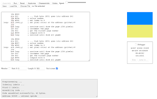
The only thing is that I was not able to do them, one of the instances of it is when I was supposed to make the middle four pixels of different colour, and I tried to make it blue, I was only able to make Ukrainian flag at max.
Conclusion: Wrapping Up
Thank you for joining me on this journey into the world of 6502 Assembly Language. I hope you've enjoyed exploring the fascinating realm of low-level programming as much as I have. Stay tuned for more adventures in the world of technology and programming!


Amazing job! I like part with Ukrainian part 👏
ReplyDelete